Centrifugal auxiliary fan with airfoil impeller for a gas-turbine package on the Jitamitra shop floor
Home  /  Applications  /  Gas-turbine inlet / aux
Applications

Gas-turbine inlet & auxiliary fans — clean air, kept reliable.

The fans around a gas turbine or genset package are not the main event — but they sit on the critical path. Inlet-air boost, enclosure and generator ventilation, and auxiliary cooling all serve a machine that costs orders of magnitude more than the fan itself, and when the fan trips the turbine trips with it. The air is clean, so erosion and corrosion are not the story; cleanliness, reliability and enclosure gas/fire safety are. We build these fans across the full envelope below — up to 2,00,000 CMH, 2,000 mmWC and 400 HP — engineered to the package, not pulled off a shelf.

2,00,000CMH max flow
2,000mmWC max static
Zone 2ATEX self-declared
400 HPdrive power
15,000+
fans built since 2011
200 HP
VFD test rig · IS 4894 / AMCA 210
99%
on-time delivery
3
working days to quote — always
AROUND THE MACHINE · CLEAN HIGH-FLOW AIR · RELIABILITY-CRITICAL · GAS/FIRE-SAFE ON APPLICATION
What it does

Three fan duties around one turbine — inlet air, enclosure ventilation, auxiliary cooling.

A gas-turbine package needs air in more than one place: an inlet-air fan boosting clean, filtered air toward the compressor face; enclosure and generator-ventilation fans purging heat and any fuel-gas leakage from the acoustic hood; and auxiliary fans cooling lube-oil, alternator and control-room loads. Each serves a machine far more valuable than itself, so each is judged on cleanliness and reliability first.

  • 01
    Supply clean

    Filtered inlet and process air toward the turbine, at low static and high flow. Downstream of the inlet filter house the residual loading is very low — the fan must add flow without adding debris, shedding or imbalance of its own.

  • 02
    Ventilate the enclosure

    Purge heat and any fuel-gas leakage from the acoustic enclosure — a typical package holds the hood at several dozen air changes an hour and pre-purges before ignition. On fuel-gas machines the ventilation path is a classified Zone 2 area.

  • 03
    Stay up

    Continuously, often 8,000+ h/yr on a machine that trips if the fan does. The duty is not hard on the wheel; it is hard on the reliability case — bearings, drive and balance carry the whole design weight.

INDUCED-DRAFT CENTRIFUGAL FAN Single-width single-inlet — scroll cut away to reveal the impeller inlet expansion joint MOTOR IE3 / VFD GAS IN GAS OUT n 1 2 3 4 5 6 7 8 9 10 1 Inlet cone (bell-mouth) 2 Backward-curved / radial-tipped impeller 3 Spiral volute casing 4 Replaceable AR wear plates (volute throat) 5 Shaft 6 Plummer-block bearings (L10 ≥ 40,000 h) 7 Shaft cooling disc (>400 °C duty) 8 Pedestal / base frame 9 Drive — motor + coupling 10 Outlet flange + duct take-off
Fig. 1Gas-turbine auxiliary centrifugal fan — single-width single-inlet, scroll cut away to reveal the airfoil impeller. Numbered components keyed below the drawing.
Why it is hard

The air is clean — so the whole design load falls on cleanliness, reliability and enclosure safety.

Nothing about this duty erodes a wheel. What makes it hard is the machine downstream: a turbine or alternator worth many multiples of the fan, that stops the moment the fan does. So the engineering shifts entirely — inlet cleanliness protects the compressor, reliability protects uptime, and on a fuel-gas package the enclosure ventilation fan sits in a classified area. A trip that would be a nuisance on a ventilation fan is a unit-outage event here.

01 — CLEANLINESS

Debris and shedding reach the compressor

Anything the inlet-air fan sheds — scale, weld spatter, coating flake, a liberated fastener — travels straight toward a compressor turning at high speed. Foreign-object damage to turbine blading is catastrophic and expensive, so the fan cannot be a source of debris.

How we engineer it out

Clean-air construction with a smooth, deburred, fully-welded flow path and controlled internal coating; airfoil or backward-curved wheels balanced to a tight grade so the fan never sheds and never generates a particle of its own. No wear liners to spall, no exposed hardware in the airstream.

02 — RELIABILITY

A fan trip is a unit trip

These fans run continuously on a machine that cannot tolerate their loss. A bearing failure, an imbalance excursion or a drive fault does not just stop the fan — it takes the turbine or genset offline, and unplanned turbine outage is measured in lakhs per hour, not the cost of the fan.

How we engineer it out

Bearing life engineered to a design target of L10h ≥ 40,000 h continuous, with duplex or N+1 fan sets on critical enclosure duty; tight balance to ISO 21940 G2.5 or G1.0, provision for vibration and bearing-temperature monitoring, and every unit proven on the rig before it ships.

03 — GAS / FIRE SAFETY

Fuel-gas leakage in the enclosure

On a fuel-gas turbine or genset the acoustic enclosure can accumulate leaked fuel gas, so the ventilation air path is a classified hazardous area. An ordinary ventilation fan is an ignition source in that space, and the ventilation system is part of the enclosure fire-and-gas safety case.

How we engineer it out

Spark-resistant construction per AMCA 99 with an ATEX Zone 2 self-declaration per 2014/34/EU (Category 3G) where the area classification calls for it — non-sparking impeller, bonded earthing and an aluminium impeller on Zone 2 service, coordinated with the package pre-purge and fire-and-gas logic.

How we design for it

Every choice is documented on the GA drawing you sign off — before we cut metal.

We don't sell a catalogue near-fit. The fan is engineered to the package — inlet cleanliness, enclosure air-change and gas classification, reliability class and sound limit — made to order, not off a shelf.

  • Clean-air construction — Airfoil-bladed or backward-curved impeller for high efficiency on clean air; smooth deburred fully-welded flow path, controlled internal coating, and no wear liners or exposed hardware in the airstream that could shed toward the machine.
  • Reliability & monitoring — Bearings sized for L10h ≥ 40,000 h continuous; duplex or N+1 sets on critical enclosure ventilation; provision for vibration and bearing-RTD monitoring so the package can trend the fan and act before it trips.
  • Enclosure gas & fire safety — Spark-resistant construction per AMCA 99 and ATEX Zone 2 self-declaration per 2014/34/EU (Cat 3G) on fuel-gas machines; aluminium impeller on Zone 2, bonded earthing, coordinated with the package pre-purge and fire-and-gas trip logic.
  • Control & efficiency — VFD default — enclosure ventilation demand tracks ambient and machine load, and speed control holds air-change rate without throttling loss; efficient wheel selection matters on a fan that runs 8,000+ h/yr beside a base-load machine.
Engineered to your duty point

We size the fan onto the stable side of its curve — then prove it on the rig.

No catalogue fan forced onto your spec. Your operating point is engineered onto the best-efficiency region of the selected wheel — high flow at low-to-moderate static for this duty — and verified on the 200 HP VFD test rig before dispatch.

avoid: unstable 0 40,000 80,000 1,20,000 1,60,000 2,00,000 VOLUME FLOW RATE  [ CMH ] 0 500 1000 1500 2000 STATIC PRESSURE  [ mmWC ] 0 25 50 75 100 STATIC EFFICIENCY  [ % ] Fan static pressure System resistance Static efficiency BEP 82% DUTY POINT 1,20,000 CMH · 450 mmWC Fan static pressure System resistance Static efficiency
Fig. 2Representative gas-turbine auxiliary-fan characteristic — fan static pressure, system resistance and static efficiency vs. flow, with the duty point engineered onto the best-efficiency region. Illustrative; every fan is sized to its own duty.
Capability envelope — gas-turbine inlet / aux service

What we can supply, and where it stretches on application.

ParameterStandardOn application
Volume flowup to 2,00,000 CMHhigher on enquiry
Static pressureup to 2,000 mmWCtypically low-to-moderate on inlet / ventilation duty
Air temperatureambient to 80 °C (enclosure ventilation)higher on hot-air auxiliary duty with special metallurgy
Inlet air cleanlinessclean, filtered — very low residual loadingclean-air flow path, no shedding by design
Static efficiencyhigh on standard buildshigher on airfoil high-efficiency builds
Construction (ignition)standard, or AMCA 99 spark-resistant on fuel-gas dutyATEX Zone 2 (Cat 3G) self-declared on application
Drive powerup to 400 HPhigher with custom motor sourcing
Balance qualityISO 21940 G6.3G2.5 / G1.0 on reliability-critical duty

The envelope above covers the great majority of gas-turbine inlet and auxiliary duty. Most of this service is clean, high-flow air at low-to-moderate static, so wear protection is not required and the design load falls on cleanliness, reliability and — on fuel-gas machines — enclosure gas/fire safety. Spark-resistant construction is per AMCA 99, combined with an ATEX Zone 2 (Cat 3G) self-declaration per 2014/34/EU where the enclosure is classified. Bearing life is a design target of L10h ≥ 40,000 h continuous, with duplex or N+1 sets and longer L10 on critical duty. For duty beyond the envelope we engineer to spec and quote on enquiry.

How a Jitamitra GTIA fan is specified

Specified, not picked from a shelf.

The same engineering language carries from your enquiry to the GA drawing to the nameplate — expressed in the standard AMCA conventions, with the spark-resistant and ATEX marking alongside where the enclosure is classified.

Specification fieldOptions
Arrangement (AMCA 99)Arr. 1 (overhung, fan bearings) / Arr. 4 (direct, motor on base) / Arr. 8 (overhung on common base) / Arr. 9 (overhung, motor side) / Arr. 10 (overhung, motor inside base) — selected by drive, access and the package footprint.
Width / inletSWSI (single width, single inlet) default; DWDI (double width, double inlet) for high inlet-air flow at low static within a tight enclosure footprint.
Wheel typeAirfoil-bladed (highest efficiency on clean high-flow air) / backward-curved (efficient, robust default) — both non-shedding clean-air constructions; forward-curved avoided on this reliability-critical duty.
Class (by pressure / outlet velocity)Class I / II / III selected from the duty point on the pressure-vs-outlet-velocity limits; higher class = heavier construction for higher pressure and tip speed.
Spark-resistant construction (AMCA 99)Type A (all non-ferrous parts in the airstream) / Type B (non-ferrous rub ring) / Type C (aligned construction preventing ferrous contact) — specified where the enclosure ventilation path is a classified fuel-gas area; standard construction on clean inlet-air duty away from classification.
Materials of constructionMild steel + epoxy coating (standard) / stainless steel for humid coastal or offshore air / aluminium impeller for ATEX Zone 2 service; smooth deburred fully-welded flow path throughout for cleanliness.
Drive & reliabilityDirect-coupled / V-belt / VFD (default for ventilation-demand control). Drive up to 400 HP; bearings sized for L10h ≥ 40,000 h; duplex or N+1 sets, and provision for vibration and bearing-temperature monitoring on critical duty.
ATEX scopeZone 2 self-declared (Cat 3G) per 2014/34/EU for fuel-gas enclosure ventilation — non-sparking impeller, bonded earthing, T-class bearing control — coordinated with the package pre-purge and fire-and-gas logic. Higher zone on application via Notified-Body partner.
Accessories & acoustic scopeIsolation / shut-off damper and flexible connection at the enclosure interface; inlet and outlet silencers with acoustic-lagged casing where the package sits near occupied space; VFD control; drain and inspection doors; vibration / bearing-RTD monitoring provision.
The proof, not the promise

We test before we ship — and you're welcome to witness it.

Every job's performance is verified at our works on the 200 HP VFD test rig, to the AMCA 210 / ISO 5801 method, before dispatch.

  • Customer-witnessed FAT on request — at no extra cost
  • Rotors balanced to ISO 21940 G6.3 as standard (G2.5 / G1.0 on application) before they leave the floor
  • Full NDT in-house — DP, MPI, UT, RT — to what the duty demands
30+ INDUSTRIES · 45 APPLICATION / DUTY TYPES
Where our gas-turbine fans run

Around the machine, where the fan protects something far more valuable.

Oil & Gas

Mechanical-drive and compression-package turbine enclosure ventilation, inlet-air boost, offshore genset-hood purge fans.

Power Generation

Simple- and combined-cycle turbine auxiliary ventilation, generator and lube-oil cooling air, inlet-house auxiliary fans.

Data Centres

Standby and prime-power genset enclosure ventilation and radiator-support air on the resilience train.

Renewables & Hydrogen

Hydrogen- and syngas-fired turbine and engine packages — classified enclosure ventilation, gas-safe construction.

Process Plants

Captive-power turbine and reciprocating-genset enclosure and auxiliary cooling fans.

Marine & Offshore

Turbine and genset machinery-space and enclosure ventilation with corrosion-resistant marine construction.

Package OEMs

Auxiliary and ventilation fans supplied as a sub-package to turbine and genset packagers — interface documented up front.

Your process

45 application/duty types engineered. Tell us yours.

Standards & conformity

Stated precisely — because procurement checks.

What our marks mean, in the words that survive an audit.

Performance

Tested to the AMCA 210 / ISO 5801 method, in-house on our 200 HP VFD rig. Tested-to-method — not AMCA-certified.

Quality system

ISO 9001:2015 — third-party certified. Our only third-party certification.

CE conformity

Self-declared per 2006/42/EC + 2014/35/EU (Module A). A self-declaration, not a notified-body certificate.

ATEX conformity

Self-declared, Zone 2/22, Category 3, per 2014/34/EU, where the area classification calls for it.

Oil & gas duty

Designed and built to API 673 as project-specific scope.

Welding

ASME Sec IX qualified welders + WPS for every joint.

Balance

ISO 21940 — G6.3 minimum, G2.5 / G1.0 on application.

Vibration

ISO 20816 evaluation; ISO 14694 for fan-specific limits.

Lead time & process

From enquiry to a tested fan on your dock.

StageStandard dutyAPI-673 / engineered
Offer / quotation3 working days — always7–10 working days
GA drawing for approval2–3 weeks from PO3–4 weeks from PO
Manufacture + balance + paint6–10 weeks10–14 weeks
Performance test + witnessed FAT~1 week1–2 weeks
Order-to-dispatch (total)9–14 weeks14–20 weeks

Shutdown-driven replacements: we have shipped fans within 6 weeks of a clean PO. Tell us your shutdown window and we commit to a dated plan.

Questions engineers ask

The eight we hear most before a PO.

What fans on a gas-turbine package do you actually build?
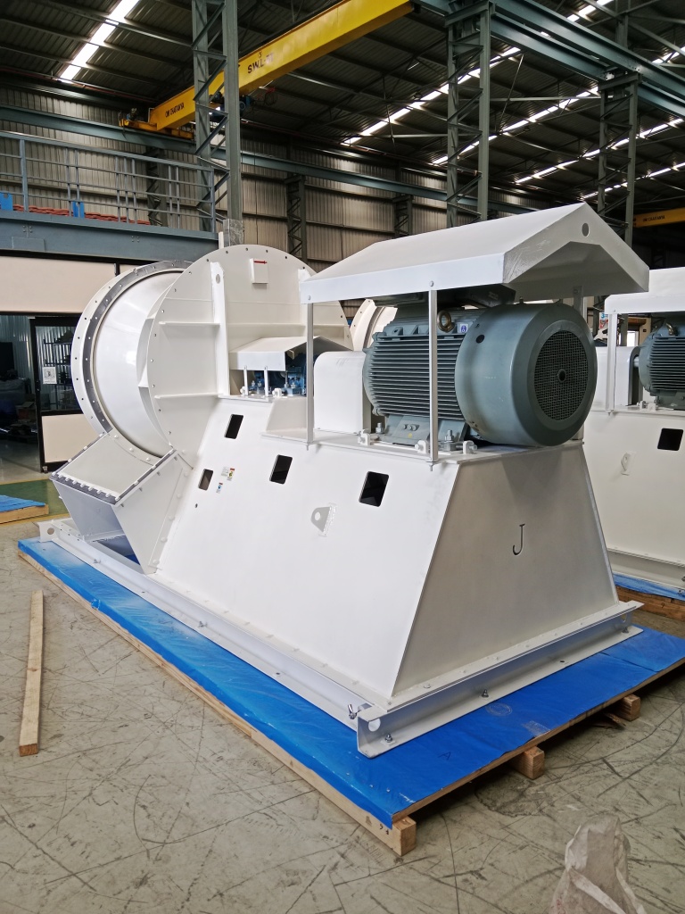
The auxiliary and ventilation fans around the machine, not the turbine itself. That covers inlet-air and process-air boost toward the compressor, acoustic-enclosure and generator-hood ventilation, and auxiliary cooling air for lube-oil, alternator and control loads. These are clean-air fans, so the engineering focus is cleanliness, reliability and — on fuel-gas machines — enclosure gas and fire safety, rather than the erosion and corrosion that dominate flue-gas duty. We have executed this duty on a handful of turbine and genset packages and engineer each fan to the package rather than offering a shelf item.
The air is clean, so what makes this a hard duty?
The machine downstream, not the air. A turbine or alternator is worth many multiples of the fan and stops the moment the fan does, so the whole design load moves to protecting it. Inlet cleanliness protects the compressor from any debris the fan might shed, reliability protects uptime because a fan trip is a unit trip, and on a fuel-gas package the enclosure ventilation fan sits in a classified hazardous area. None of that erodes a wheel, but all of it has to be engineered out, which is why we do not treat this as a generic clean-air ventilation fan.
How do you make sure the inlet fan does not send debris into the compressor?
By building the fan so it cannot become a source of foreign object damage. The flow path is smooth, deburred and fully welded with a controlled internal coating, there are no wear liners that could spall and no exposed hardware in the airstream, and the impeller is balanced to a tight grade so it never sheds material or a loosened part toward the machine. On filtered inlet air the residual loading is already very low, so our job is simply to add flow without adding a single particle of our own.
A fan trip takes the turbine offline. How do you engineer the reliability?
We treat the fan as part of the critical train. Bearings are sized to a design target of L10h at or above 40,000 hours continuous, and on critical enclosure ventilation we supply duplex or N+1 fan sets so the loss of one fan does not stop the machine. The impeller is balanced to ISO 21940 G2.5 or G1.0, we provide for vibration and bearing-temperature monitoring so the package can trend the fan and act before it trips, and every unit is performance-tested and balance-verified on the rig before it ships. Unplanned turbine outage is measured in lakhs per hour, so the reliability case is where the money is.
Our turbine burns fuel gas. Is the enclosure ventilation fan a hazardous-area fan?
Yes. On a fuel-gas turbine or genset the acoustic enclosure can accumulate leaked fuel gas, so the ventilation air path is a classified hazardous area and the ventilation system is part of the enclosure fire-and-gas safety case. For that duty we build spark-resistant construction to AMCA 99 and self-declare ATEX Zone 2 per 2014/34/EU, Category 3G, with a non-sparking aluminium impeller, bonded earthing and T-class bearing control, coordinated with the package pre-purge and fire-and-gas trip logic. On clean inlet-air duty away from the classified zone, standard construction applies.
Do you supply the fan as a sub-package to a turbine or genset packager?
Yes. We supply auxiliary and ventilation fans separately to turbine and genset packagers and enclosure builders. You specify the duty and the integration interface — flange and enclosure-opening dimensions, mounting orientation, spark-resistant type and ATEX scope, the electrical interface and the control and trip protocol — and we document it up front and deliver the fan ready to mate, coordinated with your pre-purge and fire-and-gas logic. The engineering is identical to a direct-buyer fan; only the interface and who buys it differ.
Should I specify VFD or a damper for the enclosure ventilation fan?
VFD is our default. Enclosure ventilation demand tracks ambient temperature and machine load, and speed control holds the required air-change rate without the throttling loss of a damper at part-load, which matters on a fan that runs 8,000 hours a year or more beside a base-load machine. An isolation or shut-off damper is still supplied at the enclosure interface for maintenance and for the pre-purge sequence. We quote whichever the package logic calls for.
What certifications and test standards actually apply to these fans?
To be precise about the claims: performance is tested in-house to the AMCA 210 / ISO 5801 method on our 200 HP VFD test rig — that is testing to the AMCA method, not an AMCA certification, and we are not an AMCA member. Spark-resistant construction is built to AMCA 99. CE is self-declared per the relevant EU directives, and ATEX Zone 2/22 is self-declared per 2014/34/EU, Category 3, where the area classification calls for it — those are self-declarations of conformity, not third-party certifications. Balance is to ISO 21940 (G6.3 standard, G2.5 or G1.0 on this reliability-critical duty) and bearing life is a design target of L10h at or above 40,000 hours. Our only third-party certification is ISO 9001:2015.
Across the range

Where gas-turbine inlet / aux fans fit — the fans that run them, related duties, and the industries served.

The same engineering, viewed three ways — by fan family, by duty, and by industry. Follow the cross-references.

Take it further

Specs an engineer can use — not a brochure.

Engineer to engineer

Send us the duty point.
We'll quote in 3 working days — always.

No model numbers needed. Give us the operating conditions — flow, static, gas temperature, composition, particulate, and any tender standard — and our application engineers size the fan and quote it. Attach a spec or GA if you have one.

+91 90110 09155  ·  mihir.jitamitra@gmail.com