High-alloy centrifugal induced-draft fan for waste-to-energy flue gas on the Jitamitra shop floor
Home  /  Applications  /  Waste-to-energy / incinerator ID
Applications

Waste-to-energy / incinerator ID fans — for the most corrosive flue gas in the plant.

The induced-draft fan on a municipal- or hazardous-waste incineration line pulls the whole gas train — from the boiler pass, through the APC islands, to the stack. The gas is hot, dust-laden, and above all chloride-bearing: HCl, HF, SOₓ and heavy-metal salts that a standard flue-gas fan is not built to survive. Whether the fan sits hot upstream of the scrubber or wet and saturated after it decides the metallurgy. We build WtE ID fans across the full envelope below — up to 2,00,000 CMH, 2,000 mmWC, 400 HP and 600 °C.

2,00,000CMH max flow
2,000mmWC max static
600 °Cgas temperature
400 HPdrive power
15,000+
fans built since 2011
200 HP
VFD test rig · IS 4894 / AMCA 210
99%
on-time delivery
3
working days to quote — always
DOWNSTREAM OF THE INCINERATOR · NEGATIVE DRAFT · THROUGH THE APC TRAIN · CHLORIDE-BEARING FLUE GAS TO STACK
What it does

A WtE ID fan is an induced-draft fan on the harshest gas in industry — chloride, not just fly ash.

A waste-to-energy induced-draft fan sits downstream of the incinerator: pulling flue gas out, holding the furnace and boiler pass under negative pressure, and driving it through the air-pollution-control train — quench, dry or wet scrubber, bag filter or ESP — to the stack. Position in that train decides the fan: hot and dust-laden ahead of the scrubber, or cooled, wet and saturated with acid after it.

  • 01
    Pull

    Enough gas to hold the incinerator and boiler pass under target draft — typically −10 to −30 mmWC at the furnace outlet, steady through refuse-feed swings and calorific-value variation.

  • 02
    Push

    Across the full APC-train resistance — boiler pass, quench or reactor, bag filter or ESP, wet scrubber, ID ducting and stack — which on a multi-stage waste line can total 400–2,000 mmWC.

  • 03
    Survive

    Chloride-bearing flue gas — HCl, HF, SOₓ, heavy-metal and alkali salts — at 150–350 °C hot-side, or cooled below the acid and water dew point when the fan sits after a wet scrubber.

INDUCED-DRAFT CENTRIFUGAL FAN Single-width single-inlet — scroll cut away to reveal the impeller inlet expansion joint MOTOR IE3 / VFD GAS IN GAS OUT n 1 2 3 4 5 6 7 8 9 10 1 Inlet cone (bell-mouth) 2 Backward-curved / radial-tipped impeller 3 Spiral volute casing 4 Replaceable AR wear plates (volute throat) 5 Shaft 6 Plummer-block bearings (L10 ≥ 40,000 h) 7 Shaft cooling disc (>400 °C duty) 8 Pedestal / base frame 9 Drive — motor + coupling 10 Outlet flange + duct take-off
Fig. 1WtE induced-draft fan — single-width single-inlet, scroll cut away to reveal the high-alloy impeller and drain. Numbered components keyed below the drawing.
Why it is hard

Chloride is what separates a WtE ID fan from an ordinary flue-gas fan.

Waste flue gas carries a chemistry no coal boiler produces: HCl and HF from chlorinated plastics and refuse, alkali and heavy-metal salts, and — after a wet scrubber — saturated gas sitting at its acid dew point. Specify a standard mild-steel ID fan and the chloride eats the wheel in 12–24 months; engineer the metallurgy and the dew-point margin to the actual gas analysis, and the fan runs 8+ years between wheel changes.

01 — CHLORIDE CORROSION

Acid and chloride attack on the wheel

HCl and HF condense as hydrochloric and hydrofluoric acid on any surface below the dew point, and chloride ions drive pitting and stress-corrosion cracking that plain 304 or mild steel cannot resist. The wheel — thin, fast and cyclically stressed — is where it shows first.

How we engineer it out

Metallurgy matched to the measured gas: 316L as a floor, duplex, C-276 / Hastelloy or Inconel for high chloride, or FRP-rubber-ebonite lining on the coldest wet-scrubber duty — selected against your HCl, HF and dew-point data, not a default.

02 — DEW-POINT / WET GAS

Saturated gas below the dew point

After a quench or wet scrubber the gas leaves cooled and saturated, sitting at or below its water and acid dew point. Condensate collects in the volute, sticky salt-laden slurry builds on the blades, and the wall corrodes wherever it is allowed to run cold.

How we engineer it out

Fully-drained casing with a low-point drain, a smooth corrosion-resistant flow path that sheds condensate, and — on hot-side duty — casing insulation and heat tracing to hold the wall above dew point. Special coating or lining where the gas is wet by design.

03 — STICKY DUST & FOULING

Salt-laden, sub-micron dust buildup

Waste-line dust is fine, alkaline and hygroscopic — it absorbs moisture and cakes onto the blades, unbalancing the wheel and cutting flow. Reagent carry-over from a dry scrubber (lime, activated carbon) makes it stickier still.

How we engineer it out

Radial or radial-tip self-cleaning wheel geometry that throws deposit off the blade root, bolted-in wear plates and access doors for in-place cleaning, and a shaft seal that keeps salt slurry out of the bearing housing. Wheel washing and inspection ports on request.

How we design for it

Every choice is documented on the GA drawing you sign off — before we cut metal.

We don't sell a catalogue near-fit. The fan is engineered to your gas analysis, position in the APC train, temperature and dew-point case — made to order, not off a shelf.

  • Metallurgy to the gas analysis316L floor for moderate chloride; duplex or C-276 / Hastelloy / Inconel for high HCl / HF and stress-corrosion risk; FRP construction or rubber-ebonite lining on the coldest saturated wet-scrubber duty. Wetted surfaces sized to your measured HCl, HF, SOₓ and dew point — never a generic 'stainless'.
  • Dew-point & drainage — Hot-side fans get casing insulation and heat tracing to hold the wall above the acid dew point; wet-side fans get a fully-drained volute, low-point drain and a flow path that sheds condensate. Special coating or lining where the gas is saturated by design.
  • Wheel geometry & wear — Radial-tipped backward-curved for efficiency on cleaner clean-side duty; straight-radial self-cleaning where salt and reagent fouling dominate. AR400 bolted-in wear plates and hard-faced leading edges on abrasive raw-gas duty, replaceable in place through access doors.
  • Thermal management & sealing — Fabric or metal expansion joints for growth of order ~25 mm on a long run at 350 °C; shaft cooling disc standard above 400 °C; and a purged or labyrinth shaft seal that keeps chloride-laden gas and salt slurry off the shaft and out of the bearings.
Engineered to your duty point

We size the fan where its curve crosses your system — then prove it on the rig.

No catalogue fan forced onto your spec. Your operating point is engineered onto the best-efficiency region of the selected wheel — accounting for the dust and reagent loading that shifts the system curve over a cleaning cycle — then verified on the 200 HP VFD test rig before dispatch.

avoid: unstable 0 40,000 80,000 1,20,000 1,60,000 2,00,000 VOLUME FLOW RATE  [ CMH ] 0 500 1000 1500 2000 STATIC PRESSURE  [ mmWC ] 0 25 50 75 100 STATIC EFFICIENCY  [ % ] Fan static pressure System resistance Static efficiency BEP 82% DUTY POINT 1,20,000 CMH · 450 mmWC Fan static pressure System resistance Static efficiency
Fig. 2Representative WtE ID-fan characteristic — fan static pressure, system resistance and static efficiency vs. flow, with the duty point engineered onto the best-efficiency region. Illustrative; every fan is sized to its own duty.
Capability envelope — WtE / incinerator ID service

What we can supply, and where it stretches on application.

ParameterStandardOn application
Volume flowup to 2,00,000 CMHhigher on enquiry
Static pressureup to 2,000 mmWChigher on enquiry
Continuous gas temperatureup to 600 °Chigher with refractory lining + special metallurgy
Corrosion (wetted metallurgy)316L floor; duplex / C-276 / Inconel on chlorideFRP / rubber-ebonite lining on saturated wet-scrubber duty
Inlet particulate loadinglow on clean-side; high dust load on raw-gashigher with enhanced wear protection
Drive powerup to 400 HPhigher with custom motor sourcing
Balance qualityISO 21940 G6.3G2.5 / G1.0 on application
Bearing life (design target)L10h ≥ 40,000 h continuouslonger L10 on application

The envelope above covers the great majority of WtE and incinerator ID-fan duty. For duty beyond it, we engineer to spec and quote on enquiry. Metallurgy is the design pivot: 316L is the floor, with duplex, C-276 / Hastelloy or Inconel chosen against the measured HCl, HF, SOₓ and chloride, and FRP or rubber-ebonite lining used where the gas leaves a wet scrubber saturated and cold. Inlet loading is position-dependent — typically low on clean-side ID after the bag filter or ESP, and heavy on raw-gas duty ahead of collection. Bearing life is a design target of L10h ≥ 40,000 h continuous, with longer L10 on application.

How a Jitamitra WTE fan is specified

Specified, not picked from a shelf.

The same engineering language carries from your enquiry to the GA drawing to the nameplate — expressed in the standard AMCA conventions, with the wetted metallurgy called out alongside.

Specification fieldOptions
Arrangement (AMCA 99)Arr. 1 (overhung, fan bearings) / Arr. 4 (direct, motor on base) / Arr. 8 (overhung on common base) / Arr. 9 (overhung, motor side) / Arr. 10 (overhung, motor inside base) — selected by drive, access, temperature and corrosion isolation.
Width / inletSWSI (single width, single inlet) default for WtE ID duty; DWDI (double width, double inlet) for high flow at moderate pressure on large lines.
Wheel typeRadial-tipped backward-curved (default, best efficiency on cleaner clean-side gas) / straight-radial self-cleaning (salt and reagent fouling) / backward-curved (clean-gas, high-efficiency duty after final polishing).
Class (by pressure / outlet velocity)Class I / II / III selected from the duty point on the pressure-vs-outlet-velocity limits; higher class = heavier construction for higher pressure and tip speed.
Materials of construction316L floor / duplex, C-276 / Hastelloy or Inconel for high chloride and dew-point acid / IS 2062 or 16Mo3 casing on hot raw-gas duty / FRP construction or rubber-ebonite lining on saturated wet-scrubber gas / AR400 bolted wear plates where abrasive.
DriveDirect-coupled / V-belt / VFD (default for variable-draft control). Drive up to 400 HP across the envelope; speed typically 600–1,800 RPM.
Discharge & rotation (AMCA orientation)Rotation CW or CCW (viewed from drive side) with discharge angle per AMCA — e.g. TH/BH/UB/DB — set to match your duct take-off and installed footprint.
Accessories, dew-point & corrosion scopeInlet vane damper or VFD control; special coating, special material of construction and FRP-rubber-ebonite lining for chloride and wet gas; casing insulation and heat tracing to hold the wall above dew point; fully-drained casing with low-point drain; purged or labyrinth shaft seal against salt slurry; fabric or metal expansion joints; shaft cooling disc above 400 °C; bolted-in wear plates, inspection and washing doors.
The proof, not the promise

We test before we ship — and you're welcome to witness it.

Every job's performance is verified at our works on the 200 HP VFD test rig, to the AMCA 210 / ISO 5801 method, before dispatch.

  • Customer-witnessed FAT on request — at no extra cost
  • Rotors balanced to ISO 21940 G6.3 as standard (G2.5 / G1.0 on application) before they leave the floor
  • Full NDT in-house — DP, MPI, UT, RT — to what the duty demands
30+ INDUSTRIES · 45 APPLICATION / DUTY TYPES
Where our WtE ID fans run

Engineered for the chloride-bearing end of the flue-gas train.

Waste-to-Energy

Municipal-solid-waste incineration ID, refuse-derived-fuel boiler ID, moving-grate and fluidised-bed WtE draught.

Hazardous & Medical Waste

Rotary-kiln and controlled-air incinerator ID, medical-waste and industrial-waste flue-gas fans.

Chemicals & Petrochem

Liquid- and solvent-waste incinerator ID, spent-acid and chlorinated-stream thermal oxidiser draught.

Pollution-control OEMs

ID fans supplied as a sub-package to APC-train, scrubber and stack builders — wetted metallurgy and interface documented up front.

Thermal Power

Co-fired biomass and RDF boiler ID where the fuel adds a chloride load a coal fan is not built for.

Cement & Lime

Alternative-fuel (RDF / tyre-derived) co-processing draught with elevated chloride carry-over.

Pulp & Paper

Recovery-boiler and sludge-incinerator ID on chloride-bearing streams.

Your process

45 application/duty types engineered. Tell us yours.

Standards & conformity

Stated precisely — because procurement checks.

What our marks mean, in the words that survive an audit.

Performance

Tested to the AMCA 210 / ISO 5801 method, in-house on our 200 HP VFD rig. Tested-to-method — not AMCA-certified.

Quality system

ISO 9001:2015 — third-party certified. Our only third-party certification.

CE conformity

Self-declared per 2006/42/EC + 2014/35/EU (Module A). A self-declaration, not a notified-body certificate.

ATEX conformity

Self-declared, Zone 2/22, Category 3, per 2014/34/EU, where the area classification calls for it.

Oil & gas duty

Designed and built to API 673 as project-specific scope.

Welding

ASME Sec IX qualified welders + WPS for every joint.

Balance

ISO 21940 — G6.3 minimum, G2.5 / G1.0 on application.

Vibration

ISO 20816 evaluation; ISO 14694 for fan-specific limits.

Lead time & process

From enquiry to a tested fan on your dock.

StageStandard dutyAPI-673 / engineered
Offer / quotation3 working days — always7–10 working days
GA drawing for approval2–3 weeks from PO3–4 weeks from PO
Manufacture + balance + paint6–10 weeks10–14 weeks
Performance test + witnessed FAT~1 week1–2 weeks
Order-to-dispatch (total)9–14 weeks14–20 weeks

Shutdown-driven replacements: we have shipped fans within 6 weeks of a clean PO. Tell us your shutdown window and we commit to a dated plan.

Questions engineers ask

The eight we hear most before a PO.

What makes a waste-to-energy ID fan different from an ordinary boiler ID fan?
Chloride. A coal-boiler ID fan mostly fights heat, fly-ash erosion and SO₃ acid dew point. A waste-to-energy fan fights all of that plus HCl and HF from chlorinated plastics and refuse, alkali and heavy-metal salts, and — after a wet scrubber — saturated gas at its acid dew point. Chloride drives pitting and stress-corrosion cracking that plain 304 or mild steel cannot resist, so the metallurgy is the whole design decision. We select the wetted material against your measured gas analysis rather than fitting a standard flue-gas fan to a duty it was never built for.
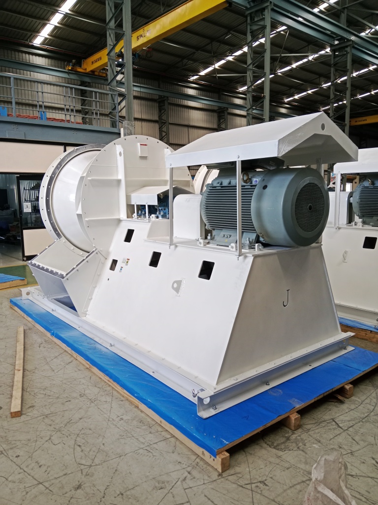
Where in the APC train does the fan sit, and why does it matter?
It decides the metallurgy and the temperature case. A hot-side ID fan sits ahead of the scrubber, handling gas at 150 to 350 °C that is dust-laden and acidic but above the dew point, so we hold the casing wall hot with insulation and tracing and pick an alloy for the chloride. A wet-side fan sits after a quench or wet scrubber, handling cooled, saturated gas sitting at or below the water and acid dew point, so it needs a fully-drained casing, a condensate-shedding flow path and often FRP or rubber-ebonite lining. Tell us the position and the gas condition at the fan and we build to it; the two positions are genuinely different fans.
We have high HCl and chloride. What materials do you use?
We match the wetted metallurgy to the measured gas. 316L is the floor for moderate chloride; for high HCl, HF and stress-corrosion risk we move to duplex stainless, C-276 (Hastelloy) or Inconel; and where the gas leaves a wet scrubber saturated and cold, an FRP construction or a rubber-ebonite lining is often the right and more economical answer. The correct choice depends on your HCl, HF, SO₂/SO₃, chloride and dew-point figures, so we size the material and the dew-point margin to your gas analysis, not to a default 'stainless'.
The gas leaves our wet scrubber saturated. How do you stop condensate corroding the fan?
Below the water and acid dew point the design changes from a hot fan to a wet one. We drain the casing fully with a low-point drain, keep the flow path smooth and corrosion-resistant so condensate sheds rather than pools, and select a wetted surface built for saturated acid gas — high alloy, FRP or a rubber-ebonite lining depending on the chemistry. Where the fan is meant to run hot we instead keep the wall above dew point with insulation and heat tracing. Which of the two applies is set by your gas condition at the fan flange, and we state it on the GA drawing.
Waste dust cakes onto the blades and unbalances the fan. How do you handle fouling?
Waste-line dust is fine, alkaline and hygroscopic, and dry-scrubber reagent carry-over (lime, activated carbon) makes it stickier, so it cakes onto the blades and throws the wheel out of balance. We default to a radial or radial-tip self-cleaning wheel that throws deposit off the blade root instead of packing it in, add bolted-in wear plates and access doors for in-place cleaning, and fit a shaft seal that keeps salt slurry out of the bearing housing. Inspection and wheel-washing ports are available where the fouling is heavy. The wear and cleaning package is sized to your loading, and on clean-side duty after the bag filter it is minimal.
Can you build a replacement to match our existing WtE fan's duty and footprint?
Yes. We reverse-engineer to the existing duty point (flow, static pressure, temperature, gas density), bearing centres, inlet and outlet orientation and foundation bolt pattern so the unit drops onto the existing base and ducting, and we take the opportunity to correct the metallurgy if the original was under-specified for the chloride. Made to your installation, not a nearest-catalogue substitute. Send the old GA, the nameplate, a recent gas analysis and a curve if you have one and we will match it.
How fast can you ship a shutdown replacement, and what is a normal lead time?
Shutdown replacements ship within 6 weeks of a clean PO where the metallurgy is a standard stainless. A standard engineered WtE ID fan runs roughly 10 to 16 weeks order-to-dispatch: GA approval 2 to 3 weeks, manufacture, balance and paint 7 to 11 weeks, test and FAT about a week. High-alloy wheels (C-276, Inconel) or a lined build add material-procurement time and run longer, so we confirm a dated commitment against your shutdown window — a real date, not a placeholder.
Do you build to API 673, CE and ATEX, and how do you test?
We design and build to API 673 for oil-and-gas and refinery-adjacent duty as project-specific scope (allow 7 to 10 working days for the offer). CE is self-declared per 2006/42/EC and 2014/35/EU, and ATEX Zone 2/22 is self-declared per 2014/34/EU (Category 3) where the area classification calls for it. To be precise, those are self-declarations of conformity, not third-party certifications. Performance is tested in-house to the AMCA 210 / ISO 5801 method on our 200 HP VFD test rig, not AMCA-certified, and every fan is balanced to ISO 21940 G6.3 as standard (G2.5 / G1.0 on application). Our only third-party certification is ISO 9001:2015.
Across the range

Where waste-to-energy / incinerator id fans fit — the fans that run them, related duties, and the industries served.

The same engineering, viewed three ways — by fan family, by duty, and by industry. Follow the cross-references.

Take it further

Specs an engineer can use — not a brochure.

Engineer to engineer

Send us the duty point.
We'll quote in 3 working days — always.

No model numbers needed. Give us the operating conditions — flow, static, gas temperature, composition, particulate, and any tender standard — and our application engineers size the fan and quote it. Attach a spec or GA if you have one.

+91 90110 09155  ·  mihir.jitamitra@gmail.com