Centrifugal secondary / overfire air fan with backward-curved impeller on the Jitamitra shop floor
Home  /  Applications  /  Secondary / Overfire Air (SA)
Applications

Secondary / overfire air fans — staged air that controls NOx and burns out carbon.

An SA / OFA fan injects a metered slug of combustion air above the primary burn zone — completing carbon burnout while holding the flame fuel-rich lower down to suppress thermal NOx. It is clean-air duty, but not an easy one: the air must be delivered at enough static to punch through the port and mix, and the fan must hold a steady curve while the staging split is trimmed against load and emissions. We build SA / OFA fans across the full envelope below — up to 2,00,000 CMH, 2,000 mmWC and 400 HP.

2,00,000CMH max flow
2,000mmWC max static
15-30%of total combustion air
400 HPdrive power
15,000+
fans built since 2011
200 HP
VFD test rig · IS 4894 / AMCA 210
99%
on-time delivery
3
working days to quote — always
ABOVE THE PRIMARY BURN ZONE · STAGED INJECTION · CLEAN AIR AT HIGH VELOCITY · FOR NOx CONTROL & BURNOUT
What it does

SA / OFA air is the second stage of combustion — and the mixing is the whole point.

A Secondary / Overfire Air fan supplies the staged fraction of combustion air injected through ports above the primary burn zone: completing carbon burnout in the upper furnace while the lower zone runs deliberately fuel-rich to hold flame temperature — and NOx formation — down.

  • 01
    Stage

    Delivers the overfire fraction — typically 15–30% of total combustion air — split off from the main combustion-air supply and injected above the burner belt to complete two-stage combustion.

  • 02
    Penetrate & mix

    Drives the air through the OFA ports at enough jet velocity — commonly 40–60 m/s at the nozzle — to cross the furnace width and mix into the rising gas, not hug the wall. Port static, not flow alone, decides whether burnout happens.

  • 03
    Trim clean

    Holds the staging split steady while it is trimmed against load, NOx and CO. Clean ambient air, not flue gas — so wear is rarely an issue and the focus shifts to curve stability, turndown and efficiency.

INDUCED-DRAFT CENTRIFUGAL FAN Single-width single-inlet — scroll cut away to reveal the impeller inlet expansion joint MOTOR IE3 / VFD GAS IN GAS OUT n 1 2 3 4 5 6 7 8 9 10 1 Inlet cone (bell-mouth) 2 Backward-curved / radial-tipped impeller 3 Spiral volute casing 4 Replaceable AR wear plates (volute throat) 5 Shaft 6 Plummer-block bearings (L10 ≥ 40,000 h) 7 Shaft cooling disc (>400 °C duty) 8 Pedestal / base frame 9 Drive — motor + coupling 10 Outlet flange + duct take-off
Fig. 1SA / OFA centrifugal fan — single-width single-inlet, scroll cut away to reveal the backward-curved impeller. Numbered components keyed below the drawing.
Why it is hard

Clean air, but three things still decide whether the staging actually works.

The gas is clean, so erosion and dew-point corrosion do not drive this duty. What does: the fan must hold a stable curve while the staging split is modulated, deliver enough port static to make the air penetrate and mix, and run efficiently on a continuous parasitic load. Get the port static wrong and the OFA air hugs the wall instead of mixing — NOx and CO both climb, and the reason is a fan sized on flow alone rather than on delivered jet velocity.

01 — MIXING

Port static and jet penetration

OFA burnout depends on the air crossing the furnace and mixing into the rising gas. Under-pressure the ports and the jet stays near the wall — carbon-in-ash and CO rise, and the NOx benefit of staging is lost.

How we engineer it out

We size to the delivered nozzle static and velocity, not flow alone — commonly 40–60 m/s at the port — carrying the full duct-plus-nozzle resistance so the fan holds the pressure the mixing needs across the operating range.

02 — STABILITY

Curve stability under staging trim

The overfire split is continuously trimmed against load, NOx and CO, so the fan works over a moving operating band. Sized onto the flat or rising part of its curve, it can stall as back-pressure swings — oscillating the staged air and destabilising the very thing it is there to control.

How we engineer it out

We engineer the duty point onto the falling, stable portion of the pressure–flow curve — typically 5–15% right of the peak — so it stays stable across the staging band, then prove the curve on the rig.

03 — EFFICIENCY

Continuous parasitic load

SA / OFA is a smaller fan than the main combustion-air unit, but it runs continuously whenever the boiler fires. A fan held a few points below its achievable efficiency burns money every hour it runs, for the life of the plant.

How we engineer it out

Backward-curved / backward-inclined wheels for high static efficiency on standard duty; airfoil-bladed impellers for higher efficiency where the run-hours justify the CAPEX. VFD default, so the staging split is set on speed rather than throttled away.

How we design for it

Every choice is documented on the GA drawing you sign off — before we cut metal.

We don't sell a catalogue near-fit. The fan is engineered to your overfire fraction, port static and velocity, turndown range and sound limit — made to order, not off a shelf.

  • Impeller geometry — Backward-curved or backward-inclined for the highest static efficiency on clean-air staged duty; airfoil-bladed on the highest-efficiency builds where the boiler runs base-load and the hours justify the CAPEX.
  • Materials — Mild steel + epoxy coating standard; stainless where the inlet air is humid (coastal) or the plant handles corrosive process air; aluminium impeller for ATEX Zone 2 service where the area classification calls for it.
  • Control — VFD as default — The overfire split is a live variable trimmed against emissions and load. VFD sets the staged flow on speed and avoids the throttling loss of an inlet damper at part-load; inlet guide vanes (IGV) remain available where fast, fine split trim against a NOx signal is wanted.
  • Warm-air & windbox handling — Where SA is drawn warm off a common windbox or tempered with a pre-heated bleed, the inlet air can run 150–250 °C — casing metallurgy, shaft thermal-growth allowance and bearing selection set to the stated inlet temperature, not a generic ambient rating.
Engineered to your duty point

We size the fan onto the stable side of its curve — then prove it on the rig.

No catalogue fan forced onto your spec. Your operating point — flow and the delivered port static — is engineered onto the falling, stable portion of the selected wheel, 5–15% right of the peak, and verified on the 200 HP VFD test rig before dispatch.

avoid: unstable 0 40,000 80,000 1,20,000 1,60,000 2,00,000 VOLUME FLOW RATE  [ CMH ] 0 500 1000 1500 2000 STATIC PRESSURE  [ mmWC ] 0 25 50 75 100 STATIC EFFICIENCY  [ % ] Fan static pressure System resistance Static efficiency BEP 82% DUTY POINT 1,20,000 CMH · 450 mmWC Fan static pressure System resistance Static efficiency
Fig. 2Representative SA / OFA-fan characteristic — fan static pressure, system resistance and static efficiency vs. flow, with the duty point engineered onto the falling, stable region right of the peak. Illustrative; every fan is sized to its own duty.
Capability envelope — SA / OFA service

What we can supply, and where it stretches on application.

ParameterStandardOn application
Volume flowup to 2,00,000 CMHhigher on enquiry
Static pressureup to 2,000 mmWCsized to port + nozzle resistance
Overfire air fraction15–30% of total combustion airper boiler staging design
Inlet air temperatureambient to 250 °C (warm windbox / tempered)higher on application with special metallurgy
Static efficiencyhigh (backward-bladed) — figures shared on enquiryhigher on airfoil high-efficiency builds
Sound level<85 dB(A) @ 1 m<75 dB(A) with acoustic enclosure
Drive powerup to 400 HPhigher with custom motor sourcing
Balance qualityISO 21940 G6.3G2.5 / G1.0 on application

The envelope above covers the great majority of SA / OFA-fan duty. Most SA fans handle clean ambient or warm windbox air, so wear protection is rarely required; inlet temperature only matters where the staged air is drawn warm or tempered, where it can reach 150–250 °C. What sets this duty apart is the port: static is sized to the duct-plus-nozzle resistance that drives jet velocity, not flow alone, so the OFA air penetrates and mixes. Bearing life is a design target of L10h ≥ 40,000 h continuous, with longer L10 on application. For duty beyond the envelope we engineer to spec and quote on enquiry.

How a Jitamitra SA fan is specified

Specified, not picked from a shelf.

The same engineering language carries from your enquiry to the GA drawing to the nameplate — expressed in the standard AMCA conventions.

Specification fieldOptions
Arrangement (AMCA 99)Arr. 1 (overhung, fan bearings) / Arr. 4 (direct, motor on base) / Arr. 8 (overhung on common base) / Arr. 9 (overhung, motor side) / Arr. 10 (overhung, motor inside base) — selected by drive, access and temperature.
Width / inletSWSI (single width, single inlet) default for SA / OFA duty; DWDI (double width, double inlet) for high flow at moderate pressure on large windbox supply.
Wheel typeBackward-curved or backward-inclined (default, best efficiency on clean staged air) / airfoil-bladed (highest-efficiency, large continuous base-load builds).
Class (by pressure / outlet velocity)Class I / II / III selected from the duty point on the pressure-vs-outlet-velocity limits; higher class = heavier construction for the higher port static and tip speed.
Materials of constructionMild steel + epoxy coating (standard) / stainless steel for humid coastal or corrosive process air / upgraded casing metallurgy for warm windbox air / aluminium impeller for ATEX Zone 2.
DriveDirect-coupled / V-belt / VFD (default for staging-split control). Drive up to 400 HP across the envelope; speed typically 600–1,800 RPM.
Discharge & rotation (AMCA orientation)Rotation CW or CCW (viewed from drive side) with discharge angle per AMCA — e.g. TH/BH/UB/DB — set to match your OFA duct take-off and installed footprint.
Accessories & acoustic scopeInlet guide vanes (IGV) or VFD control for split trim; discharge / isolation damper; inlet and outlet silencers for low-frequency content and casing-wall acoustic lagging; acoustic enclosure for <75 dB(A); flexible connection / expansion joint on warm-air service; drain and inspection doors.
The proof, not the promise

We test before we ship — and you're welcome to witness it.

Every job's performance is verified at our works on the 200 HP VFD test rig, to the AMCA 210 / ISO 5801 method, before dispatch.

  • Customer-witnessed FAT on request — at no extra cost
  • Rotors balanced to ISO 21940 G6.3 as standard (G2.5 / G1.0 on application) before they leave the floor
  • Full NDT in-house — DP, MPI, UT, RT — to what the duty demands
30+ INDUSTRIES · 45 APPLICATION / DUTY TYPES
Where our SA / OFA fans run

Wherever staged combustion controls NOx and completes burnout.

Power Generation

Utility and cogen boiler overfire-air systems, two-stage combustion on PC and travelling-grate boilers.

Sugar & Distilleries

Bagasse-fired boiler secondary and overfire air for high-moisture-fuel burnout.

Pulp & Paper

Recovery and power-boiler secondary air, biomass-boiler overfire air.

Chemicals & Petrochem

Process-boiler and fired-heater staged combustion air for NOx compliance.

Biomass & Waste-fuel Boilers

Overfire air on grate and fluid-bed units burning agro-residue, RDF and mixed biomass.

Iron & Steel

Reheating-furnace and process-boiler staged combustion air.

Food Processing

Solid-fuel and biomass boiler secondary / overfire air for steam raising.

Your process

45 application/duty types engineered. Tell us yours.

Standards & conformity

Stated precisely — because procurement checks.

What our marks mean, in the words that survive an audit.

Performance

Tested to the AMCA 210 / ISO 5801 method, in-house on our 200 HP VFD rig. Tested-to-method — not AMCA-certified.

Quality system

ISO 9001:2015 — third-party certified. Our only third-party certification.

CE conformity

Self-declared per 2006/42/EC + 2014/35/EU (Module A). A self-declaration, not a notified-body certificate.

ATEX conformity

Self-declared, Zone 2/22, Category 3, per 2014/34/EU, where the area classification calls for it.

Oil & gas duty

Designed and built to API 673 as project-specific scope.

Welding

ASME Sec IX qualified welders + WPS for every joint.

Balance

ISO 21940 — G6.3 minimum, G2.5 / G1.0 on application.

Vibration

ISO 20816 evaluation; ISO 14694 for fan-specific limits.

Lead time & process

From enquiry to a tested fan on your dock.

StageStandard dutyAPI-673 / engineered
Offer / quotation3 working days — always7–10 working days
GA drawing for approval2–3 weeks from PO3–4 weeks from PO
Manufacture + balance + paint6–10 weeks10–14 weeks
Performance test + witnessed FAT~1 week1–2 weeks
Order-to-dispatch (total)9–14 weeks14–20 weeks

Shutdown-driven replacements: we have shipped fans within 6 weeks of a clean PO. Tell us your shutdown window and we commit to a dated plan.

Questions engineers ask

The eight we hear most before a PO.

What is the difference between secondary air, overfire air and forced-draft air?
They are stages of the same combustion-air supply. Forced-draft (FD) air is the primary combustion air pushed into the burner belt. Secondary air is the portion added to complete combustion around and above the burners. Overfire air (OFA) is the staged fraction injected through dedicated ports above the primary burn zone specifically to control NOx: the lower furnace is run deliberately fuel-rich to hold flame temperature and NOx down, and the OFA completes carbon burnout higher up. On many boilers the same fan supplies the secondary and overfire duty, which is why we treat them as one page. The FD fan is a separate, larger unit — see the Forced Draft page.
How much of the total combustion air does the overfire fan carry?
Typically 15 to 30 percent of the total combustion air, depending on the fuel, the boiler and the NOx target — the rest is primary and secondary air through the burner belt. The exact split is a live control variable, trimmed against load, NOx and CO, so we do not size the fan on a single fixed point. We size it to hold the required port static and velocity across the whole staging band you operate over.
Why does port static matter more than flow on this duty?
Because overfire burnout depends on the air actually crossing the furnace and mixing into the rising gas, not just entering it. The air has to leave the OFA nozzles fast enough — commonly 40 to 60 m/s — to penetrate to the far wall and mix. That jet velocity is set by the static the fan delivers at the port, after the duct and nozzle resistance. Size on flow alone and under-pressure the ports, and the air hugs the near wall: carbon-in-ash and CO climb and the NOx benefit of staging is lost. We size to the delivered nozzle static and velocity, carrying the full duct-plus-nozzle resistance.
How do you keep the fan stable while the staging split is trimmed?
The overfire split moves continuously as the control system trims it against load, NOx and CO, so the fan operates over a band rather than a fixed point. A fan sized onto the flat or rising part of its curve can stall as the back-pressure swings, which oscillates the staged air and destabilises the emissions control it exists to provide. We engineer the duty point onto the falling, stable portion of the pressure-flow curve, typically 5 to 15 percent to the right of the peak, so it stays stable across the band. We then verify the curve on the 200 HP VFD test rig before dispatch.
Should I specify VFD or inlet guide vanes for the staging control?
VFD is our default. The overfire split is a live variable and VFD sets the staged flow on speed, which is more efficient than throttling across the operating range because it avoids the part-load throttling loss. Inlet guide vanes (IGV) are available and are sometimes preferred where the control loop wants fast, fine trim of the split against a NOx signal without changing motor speed. We quote whichever your combustion-control philosophy calls for, or both where the loop mixes coarse and fine trim.
Can your SA / OFA fans handle warm air off a common windbox?
Yes. Where the staged air is drawn warm off a common windbox or tempered with a pre-heated bleed, the inlet air can run 150 to 250 °C. We upgrade the casing metallurgy, size the shaft for thermal growth, and select bearings for the sustained housing temperature that follows. Most SA fans, though, handle clean ambient air, so the build is simpler than an ID or pre-heated-air FD fan. We build to your stated inlet temperature and excursion case, not a generic rating.
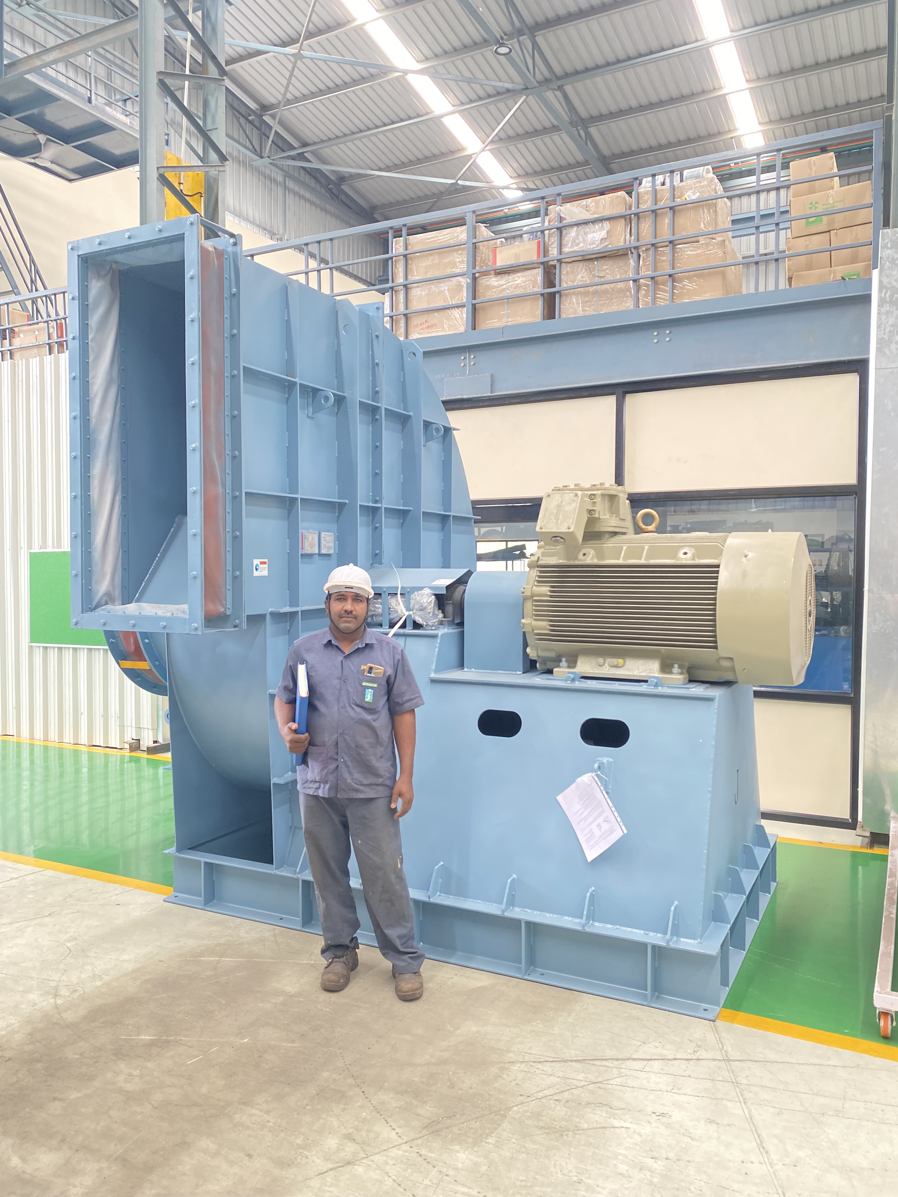
Have you built secondary / overfire air fans before?
This is an engineered-capability page, so we will be straight with you: secondary and overfire air is a staged-combustion variant of the combustion-air and forced-draft duty we build routinely across power, sugar, pulp and paper and process boilers. We engineer the SA / OFA fan to your staging design — overfire fraction, port static and velocity, turndown and inlet temperature — rather than pointing you at a fixed reference. Tell us your duty and we will engineer to it. A credible single source names its own boundaries before you discover them.
Do you build to CE and ATEX requirements, and how are your test claims stated?
Where the area classification calls for it, ATEX Zone 2/22 is self-declared per 2014/34/EU (Category 3), with an aluminium impeller on Zone 2 service; CE is self-declared per 2006/42/EC and 2014/35/EU. To be precise, those are self-declarations of conformity, not third-party certifications. Performance is tested in-house to the AMCA 210 / ISO 5801 method on our 200 HP VFD rig — that is testing to the method, not an AMCA certification, and we are not an AMCA member. Balancing is to ISO 21940 G6.3 as standard, with G2.5 or G1.0 on application, and bearing life is a design target of L10h at or above 40,000 h. Our only third-party certification is ISO 9001:2015.
Across the range

Where secondary / overfire air fans fit — the fans that run them, related duties, and the industries served.

The same engineering, viewed three ways — by fan family, by duty, and by industry. Follow the cross-references.

Take it further

Specs an engineer can use — not a brochure.

Engineer to engineer

Send us the duty point.
We'll quote in 3 working days — always.

No model numbers needed. Give us the operating conditions — flow, static, gas temperature, composition, particulate, and any tender standard — and our application engineers size the fan and quote it. Attach a spec or GA if you have one.

+91 90110 09155  ·  mihir.jitamitra@gmail.com