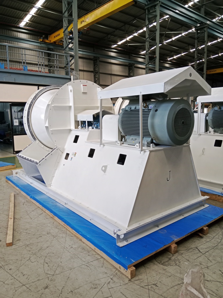
What makes a clinker-cooler fan different from an ordinary supply-air fan?
The air going in is clean and ambient, but the duty is not a plain clean-air job. The fan forces high volumes of air up through a live bed of hot clinker on a grate cooler, so the system resistance moves as clinker size, bed depth and grate loading change through the day. Fine clinker dust drops back through the grate and is re-entrained into the airstream, abrasive and hot near the bed. So we design for curve stability across a shifting bed, for abrasion from the return dust, and for elevated near-bed temperature, rather than treating it as ambient supply air. Tell us the bed resistance, air volume per compartment and near-bed temperature and we engineer to them.
How do you keep airflow steady when the clinker bed resistance keeps moving?
Bed resistance shifts with clinker granulometry, bed depth and grate loading, so the system operating point wanders through the day. A fan sized onto the flat or rising part of its curve can hunt as the point moves, starving or over-cooling a compartment and hurting kiln heat recovery. We engineer each undergrate duty onto the falling, stable portion of the pressure-flow curve, typically 5 to 15 percent to the right of the peak, so airflow per compartment stays predictable. We then verify the curve on the 200 HP VFD test rig before dispatch.
The return air carries abrasive clinker dust. How do you protect the fan?
Fine clinker fragments drop back through the grate and are re-entrained, and clinker is hard and angular, so uneven erosion throws a curved wheel out of balance before it wears through. We choose a backward-inclined or radial-tipped wheel for dust tolerance, hard-face the blade leading edges with chrome carbide on severe grit, and bolt in AR400 wear plates at the volute throat and outlet with hinged access doors so they can be replaced in place, not cut out and re-welded. The wear package is sized to your re-entrained dust loading, and on the cleaner positions upstream of the grate it is usually not needed.
How hot can the fan run near the clinker bed?
The air drawn into an undergrate fan is close to ambient, but the fan sits near a bed that has just left the kiln, so radiant and conducted heat plus hot re-entrained dust push the inlet-air and casing temperature above ambient. On the hottest near-bed and clinker-transport-air positions the fan is rated up to 600 °C at the ceiling of the envelope. We upgrade the casing to IS 2062 or 16Mo3, size the shaft for thermal growth, fit a shaft cooling disc above 400 °C, and select bearings for a sustained 80 to 100 °C housing temperature. The build is engineered to your stated near-bed temperature and excursion case, not a generic rating.
Should I specify VFD or an inlet vane damper for control?
VFD is our default. Cooling-air demand tracks clinker production rate and bed depth, and each grate compartment wants its own controllable air split, so speed control lets the fan hold airflow per compartment as the bed moves instead of throttling against a damper and wasting the loss at part-load. Inlet vane dampers remain available for legacy grate-cooler retrofit where the existing motor and starter cannot accommodate a drive. We quote whichever your installation calls for.
Can you build a replacement to match our existing cooler fan's duty and footprint?
Yes. We reverse-engineer to the existing duty point (flow, static pressure, temperature, density), bearing centres, inlet and outlet orientation and foundation bolt pattern so the unit drops onto the existing base and undergrate ducting. Made to your installation, not a nearest-catalogue substitute. Send the old GA, nameplate and a curve if you have one, along with the compartment it feeds, and we match it.
This is a new duty for us — what standards and certifications actually apply, and can you engineer it without a prior reference?
Yes. We engineer clinker and product cooling fans to your duty from first principles on our proprietary fan-selection software, whether or not we have run an identical bed before; tell us your air volume, bed resistance, near-bed temperature and dust return and we design to them. On the claims, to be precise: performance is tested in-house to the AMCA 210 / ISO 5801 method on our 200 HP VFD test rig, which is a test method, not an AMCA certification, and we are not an AMCA member. CE is self-declared per 2006/42/EC and 2014/35/EU, and ATEX Zone 2/22 is self-declared per 2014/34/EU (Category 3) where the area classification calls for it — those are self-declarations of conformity, not third-party certifications. Our only third-party certification is ISO 9001:2015. Balance is to ISO 21940 G6.3 as standard, G2.5 or G1.0 on application, and bearing life is a design target of L10h at or above 40,000 hours.
What is the lead time for a clinker-cooler fan?
A standard engineered cooling fan runs roughly 9 to 14 weeks order-to-dispatch: offer in 3 to 5 working days, GA drawing 2 to 3 weeks from PO, manufacture, balance and paint 6 to 10 weeks, and performance test plus FAT about a week. A matched bank of compartment fans or a hot near-bed build with wear and thermal scope runs a little longer. The test and FAT are customer-witnessed on request — you see the curve and the balance report before the fan leaves the floor.